Nand Gate Internal Diagram
Cmos transistor schematic nand circuit calcul electronique Nand gate nmos logic transistor schematic using digital universal ic schematics symbols its two given below Nand gate schematic diagram
A standard digital CMOS NAND3 gate and its internal transistor
Nand plc A standard digital cmos nand3 gate and its internal transistor Nand gate layout input draw lw
Digital logic nand gate(universal gate),its symbols & schematics
Nand gate logic transistors circuit transistor bjt using input gates circuits truth table schematic tutorial does work electrical digital inputsNand gate ic 7400 structure internal nor numbering go back quad component ics show Plc scada academy: basic nand gate operation explanation using theNand gate circuit diagram and working explanation.
74hct20 dual 4-input nand gate working, pinout, features and datasheetVhdl tutorial – 5: design, simulate and verify nand, nor, xor and xnor Gate nand quad circuitsLogic nand gate tutorial with nand gate truth table.
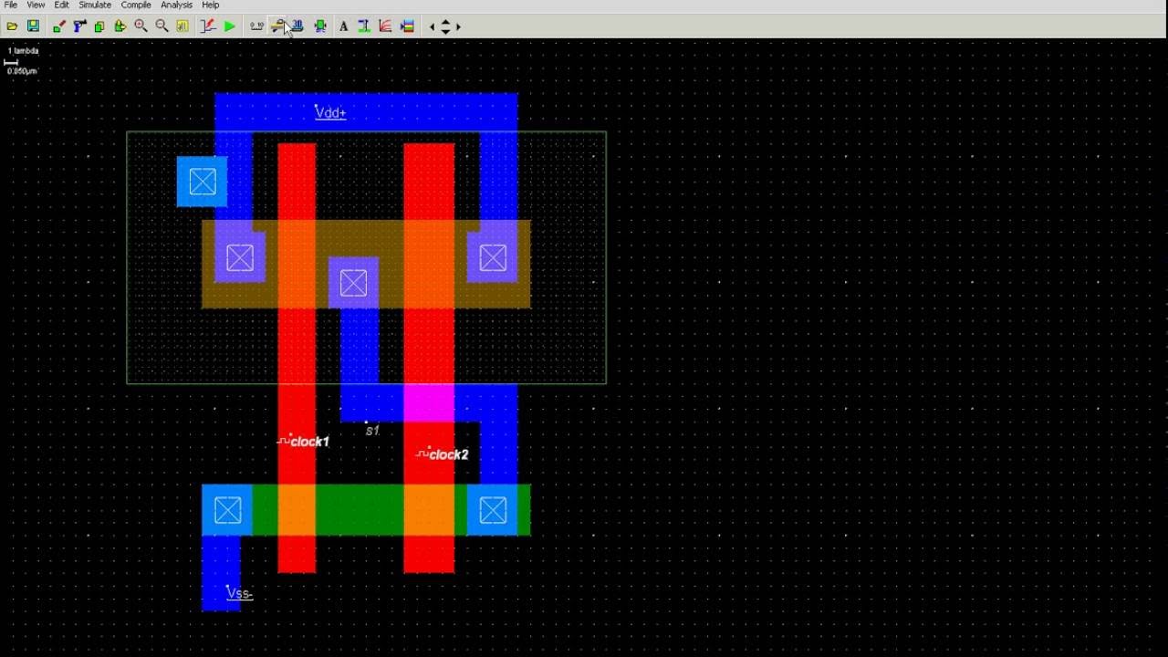
How to draw 2 input nand gate layout in microwind
Gate nand datasheetCircuit diagram of not gate using nand Nand xor logic nor xnor vhdl verify circuits simulate wiring transistor engineersgarage inverter scosche inputs cktNand gate diagram circuit ic 74ls00 pinout gates logic circuits chip not input circuitdigest working diagrams explanation electronic using limitations.
Xor nand logic nor gates xnor circuit vhdl simulate verify truth input circuits tutorial engineersgarage inverter scosche inputs ckt combinedNand gate .


Nand Gate Schematic Diagram | wiring next project

Logic NAND Gate Tutorial with NAND Gate Truth Table

VHDL Tutorial – 5: Design, simulate and verify NAND, NOR, XOR and XNOR

NAND Gate Circuit Diagram and Working Explanation

Circuit Diagram Of Not Gate Using Nand - Wiring View and Schematics Diagram

A standard digital CMOS NAND3 gate and its internal transistor

PLC SCADA ACADEMY: Basic NAND gate operation explanation using the

Digital Logic NAND Gate(Universal Gate),Its Symbols & Schematics

74HCT20 Dual 4-Input NAND Gate Working, Pinout, Features and Datasheet